1. System Overview
The 3R‑2 is a welded steel sim racing chassis constructed from heavy‑wall Hollow Structural Section (HSS) tubing. The system is engineered to maximize rigidity, minimize structural deflection, and maintain high‑frequency tactile conduction through its Immersive Frame Resonance (IFR) architecture.
The chassis incorporates a unified welded structural arch, friction‑drilled and form‑tapped (FDFT) interfaces, and a diamond‑rotated telescoping mechanism engineered for precise, play‑free adjustment.
Chassis Weight: 31.75 kg (70 lbs)
Footprint: 1200 mm × 560 mm (47″ x 22″)
Material: CSA 44W Steel
Manufacturing: CNC‑cut, welded, friction‑drilled, form‑tapped
Primary Design Goals:
• High structural rigidity
• High tactile bandwidth (IFR)
• Rapid ergonomic adjustability


2. Structural Architecture
2.1 Unified Structural Joint
The chassis uses one primary structural joint connecting the tower assembly to the base frame.
Joint Characteristics:
• Four M8 Grade 8.8 bolts
• Welded 6 mm steel interface plate
• Four FDFT M8 threaded ports
• No through‑bolts used anywhere in the system
This joint provides repeatable alignment and maintains rigidity equivalent to a welded connection.
2.2 Welded Frame Components
The following assemblies are fully welded:
• Base frame
• Seat rail structure
• Tower assembly
Tower Assembly Construction
• Uprights: 2″ × 1″ × 0.1″ HSS
• Crossbar: 2″ × 2″ × 0.1″ HSS
• Geometry: Unified welded arch
• Arm pivot welded directly to crossbar
This configuration creates a continuous load path from wheel deck to base frame, minimizing torsional and bending deflection under high‑torque steering loads.
3. Immersive Frame Resonance (IFR)
IFR is the chassis’ high‑bandwidth tactile conduction system.
The welded HSS structure preserves the full frequency range of:
• Direct Drive wheelbases
• Haptic exciters
• Pedal vibration systems
Key Properties:
• No friction‑joint damping
• No T‑nut slip or micro‑movement
• Continuous steel conduction path
• High‑frequency resonance preservation
Aluminum profile rigs introduce damping through friction‑based joints; the 3R‑2 does not.
4. Mechanical Performance
4.1 Rigidity and Deflection Control
The chassis is engineered for:
• Negligible horizontal sway
• Extremely low torsional creep under load
• Silent structural behavior (creaks, pops, joint slip)
• 500 lb static vertical load capacity
4.2 Motion‑Native Behavior
System Mass: 70 lbs
Design Logic: Low mass + high rigidity = reduced actuator latency.
The chassis supports high‑fidelity motion systems by minimizing inertia and eliminating structural flex that would otherwise absorb motion impulses.
5. Geometry & Ergonomics
5.1 Pedal Deck System
Five‑component assembly constructed from 3 mm folded steel.
Adjustments:
- 180 mm fore‑aft travel
- 20° tilt
- 508 mm clear mounting
- Independent rail spacing
Components:
- Left rail
- Right rail
- Fore and aft bridge rails
- 152 mm × 508 mm heel plate on 25 mm standoffs
5.2 Wheel Arm Assembly
- 25° arm tilt
- 30° wheel tilt
- 400 mm telescoping travel
5.2.1 Precision Telescoping System
- Diamond‑rotated HSS interface designed to eliminate lateral and rotational play.
- 45° rotated HSS profile
- Mechanical Characteristics:
- Self‑centering V‑block geometry
- Effectively no lateral play
- No rotational slop
- Extremely minimal micro‑flex under Direct Drive torque
- Rigid lock via M8 handle
- This geometry is unique to the 3R‑2 and is a major contributor to IFR performance.
5.3 Seat System
- Supported seat types:
- Bucket seats (bottom-mount patterns within range and side-mounting with optional side-mount plate)
- Automotive seats
- You can even mount an office chair
- Tilt adjustment
- Range: 0-12°
- Rail Spacing Compatibility
- Minimum bolt pattern: 21 mm × 50 mm
- Maximum bolt pattern: 448 mm × 542 mm
- Mounting slot geometry: elongated mounting slots allow fine fore‑aft and lateral positioning within the full range.
5.4 Tower Arch Positioning
Fore–Aft Adjustment
- 100 mm incremental positioning — the arch mounts through fixed hole sets on each side. Four fore–aft positions, spaced at 100 mm, let the wheel column be placed closer or further from the seat in clear, repeatable steps.
- 400 mm total adjustment range — supports compact seating through extended‑reach layouts, giving drivers the ability to set the wheel column where it naturally fits their posture and cockpit geometry.
Bolt-up Mounting
- Four‑bolt fastening — two bolts per side secure the arch directly to the base structure. Adjustment is straightforward: remove the bolts, shift the arch to the next hole set, and reinstall.
- Consistent alignment — the fixed hole pattern keeps the wheel column square to the driver across all positions, maintaining predictable steering placement after each adjustment.
5.5 REST – Rapid Ergonomic State Transition (REST)
• Rapid ergonomic adjustments: <120 seconds
• Telescoping wheel arm adjusts without tools
• Seat and pedal adjustments require a 13 mm wrench
• No disassembly required
• Supports multiple driving ergonomics within the rig’s intended geometry
What this means
You can quickly change your driving position without taking the rig apart. The wheel arm moves by hand, while the seat and pedals adjust with a simple 13 mm wrench. Everything shifts fast and cleanly, letting you dial in your preferred driving posture in under two minutes.
6. Compatibility
6.1 Wheelbase
• Universal plate
• 78.4 mm slot spacing
• Custom plates available
6.2 Pedals
• Fully slotted 508 mm rails
• Independent spacing
• Optional additional rails
6.3 Accessories
Extrusion rails supported for:
• Shifters
• Handbrakes
• Button boxes
• Keyboard trays
• Custom mounts ..and more
Extrusion is used only for non‑structural peripherals.
7. Manufacturing & Finish
7.1 Fabrication
• CNC‑cut steel
• Precision welding
• Friction‑drilled ports
• Form‑tapped threads
• Heavy‑wall HSS
• No through‑bolts
7.2 Finish
• Black semi‑gloss powder coat
• Azure Blue branding decals
• Optional accent colors
8. Quality Assurance & Assembly
8.1 QA
Each chassis is fully assembled before shipping to verify:
• Structural alignment
• Component fit
• Thread integrity
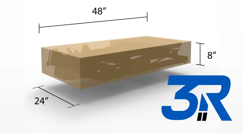
8.2 Shipping
• Single box
• 1200mm × 609mm × 203 mm – 48” x 24” x 8”
• 32 kg – 70 lbs
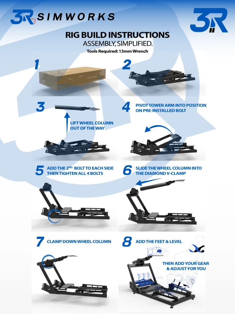
8.3 End‑User Assembly
Tools Required: 13 mm wrench
Assembly Time: <15 minutes
With the chassis pre‑assembled and verified in‑house, setup is just a quick reconnection of the parts removed for shipping — then you add your gear, connect up, and go.
Procedure:
- Open box & unpack rig
- Lift the wheel column out of the way
- Remove 2 forward tower‑to‑rail bolts
- Rotate tower on rear bolts & align with front holes
- Reinstall bolts & torque
- Slide the wheel column into the diamond V-clamp and clamp down
- Add feet & level
- Then add your gear & adjust for you
Less Time Building. More Time Racing.
8.4 Warranty
Lifetime Structural Warranty
The 3R‑2 is built to last. We don’t expect structural or threaded failures to ever happen—but if they do, we’ve got your back. If a welded or threaded part ever fails, we’ll take care of it. Just get the part to us—we’ll repair it or replace it and make sure everything is right before it goes back to you.
9. Technical Comparison
| Feature | 3R‑2 (Unified Steel) | Aluminum Profile Rigs |
| Structural Architecture | Welded and bolted HSS steel frame | Modular T‑slot extrusion |
| Primary Joint Type | FDFT M8 structural threads | T‑nuts, corner brackets |
| Rigidity | High (fixed‑geometry load paths) | Variable (joint‑dependent) |
| Tactile Behavior | High bandwidth (IFR) | Damped by friction‑based joints |
| Motion Performance | Low inertia, low latency | Higher inertia, slower response |
| Deflection Under Load | Near zero | Noticeable at joints |
| Telescoping System | Diamond‑rotated, self-centering, self-seating HSS | Not typically available |
| Ergo Adjustability | <120 sec – 13mm Wrench | Minutes, requires tools |
| Setup Time | <15 min | Hours |
| Thread Strength | 3× depth, structural | Shallow T‑nuts, risk of slip |
| Mechanical Noise | None (no joint creep) | Common (creaks, pops) |
| Accessory Mounting | Steel core + extrusion peripherals | Full extrusion |
| Long‑Term Stability | High (no joint loosening) | Requires periodic re‑torque |
| Weight | 70 lb | 100–200+ lb |
| Shipping | 1 box, 70 lb + packing materials | Multi‑box, heavy |
| Structural Integrity | Unified welded and bolted frame | Modular construction with joint instability |
10. System Summary
The 3R‑2 is a welded steel sim racing chassis engineered for:
• High rigidity
• High tactile bandwidth (IFR)
• Low inertia
• Negligible deflection under load
• Rapid ergonomic transitions
• Industrial‑grade durability
The 3R‑2 is welded where structural certainty is required and bolted where modular adjustability is essential. Fixed‑geometry components such as the seat rail structure and tower arch are fully welded for maximum stiffness, while user‑adjustable interfaces — wheel, seat, and pedal mounting — use precision FDFT bolted connections for repeatable, tool‑friendly adjustment.
Its unified steel architecture, diamond‑rotated telescoping arm, and friction‑drilled structural threads differentiate it from modular aluminum systems, providing superior tactile clarity, structural certainty, and operational efficiency.
11. Technical Data Block
| Parameter | Specification |
| Model | 3R-2 (Successor to 3R-1) |
| Material | Welded CSA G40.21 44W Structural Steel (HSS) |
| Weight | 70 lbs (32 kg) |
| Shipping Dimensions | 48″ x 24″ x 8″ (Single Box) |
| Torque Rating | Tested to a static 30Nm+ (No Discernible Twist) |
| Vertical Load | 500 lbs Static |
| Tower Adjustment | 100mm Increments (Bolted FDFT points) |
| Pedal Tilt | 20° Universal Adjustability |
| Accessory System | Supports 8020/Aluminum Extrusion |
| Motion Ready | Yes (Proprietary System in Development) |